Fiber Optic Cabling
Fiber is how you move serious bandwidth between buildings, floors, and closets. We install, terminate, splice, and test single-mode and multi-mode fiber for backbones that hold up.
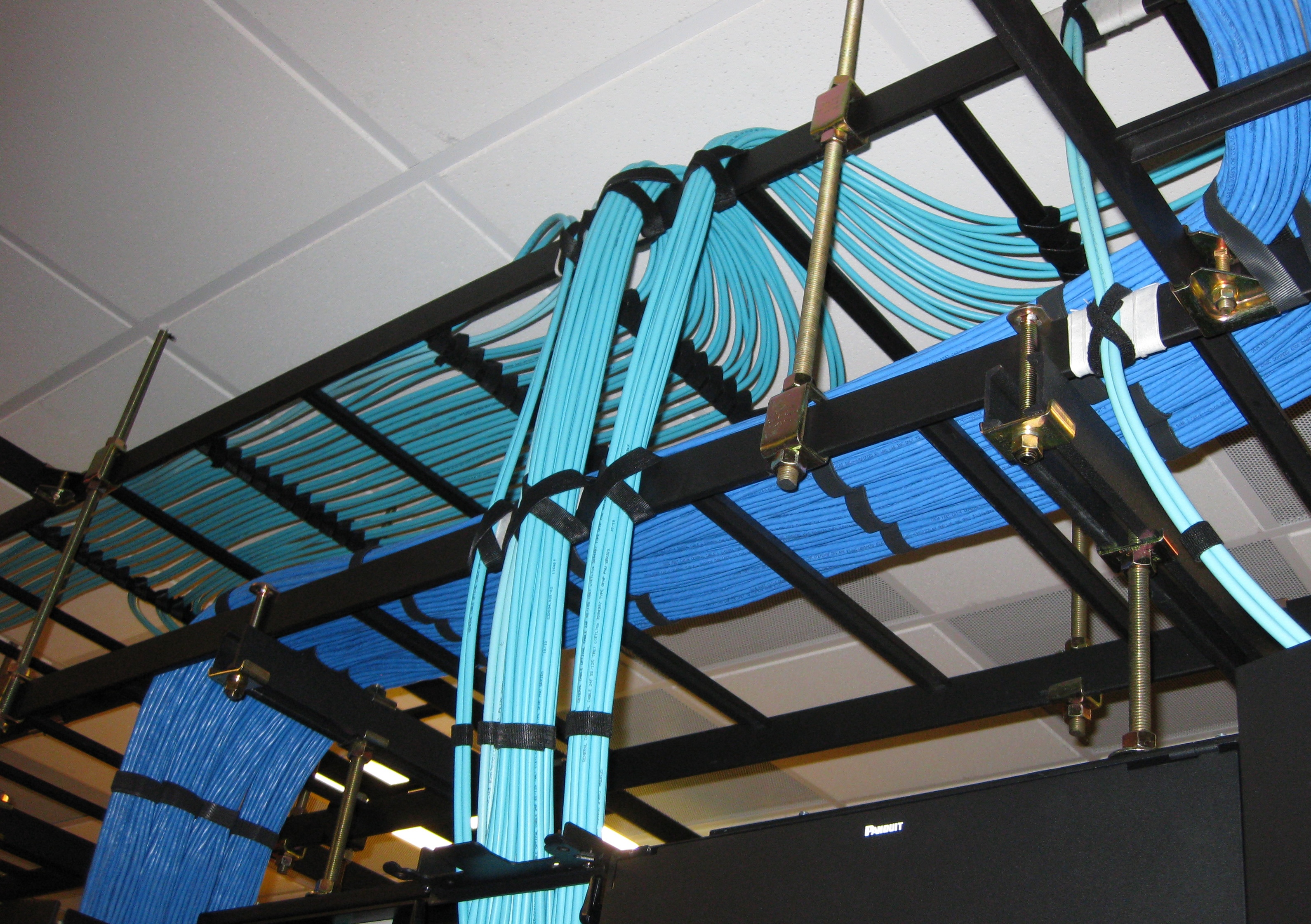
Copper is the right call for horizontal drops. Fiber is what carries the load between IDFs, buildings, and the data center. That takes clean pulls, correct connector polish, and real optical testing, and none of those are steps you can skip.
We handle riser and backbone design, fusion splicing, connectorization, and OTDR and loss testing. Every link gets documented so the next change order doesn't turn into archaeology.
What you get
- Single-mode or multi-mode chosen for the actual reach and speed
- Fusion splicing for low loss, mechanical splices for field repairs
- OTDR traces and insertion-loss results for every fiber
- Enclosures, cassettes, and pigtails organized for service
- Port-to-port maps documented and handed to your team
What we install and support.
Single-mode & multi-mode
OS2, OM3, and OM4 chosen for the reach and speed you need.
Backbone & riser design
Campus, building, and IDF-to-IDF paths planned with room to grow.
Fusion & mechanical splicing
Low-loss fusion splicing in enclosures, mechanical splices for field repairs.
OTDR & loss testing
Every fiber tested end to end, with results archived.
Cassettes & panels
LC, SC, and MPO cassettes dressed and labeled per port.
Innerduct & pathway
Innerduct, tray, and firestopping through walls and floors.
Where this work belongs.
We work across commercial property types throughout Tampa Bay and Florida. If your building type isn't listed here, call and ask.
A repeatable process, from walk to handoff.
Assess
Distances, speeds, and existing pathways set the fiber type and count.
Design
Backbone routes, splice points, and connector strategy.
Pull
Riser, plenum, or outside-plant fiber pulled at the correct tension.
Splice / terminate
Fusion splicing, cassette install, and pigtail prep.
Test
OTDR trace and insertion-loss measurement in each direction.
Document
Port maps, splice logs, and loss reports delivered.
Details that matter on site.
Single-mode vs. multi-mode
Single-mode (OS2) is the default for long runs and high-speed uplinks. Multi-mode (OM3 or OM4) is fine for shorter in-building runs and can cost less once you factor in optics. We pick based on distance, the speed you're planning for, and whatever plant is already in the building.
Why fusion splicing matters
Fusion splices usually land around 0.05 to 0.1 dB of loss, well under what a mechanical splice gives you, and they hold that number over time. On a backbone link that headroom is what keeps the network from slowly drifting out of spec a few years in.
What clean installs look like.
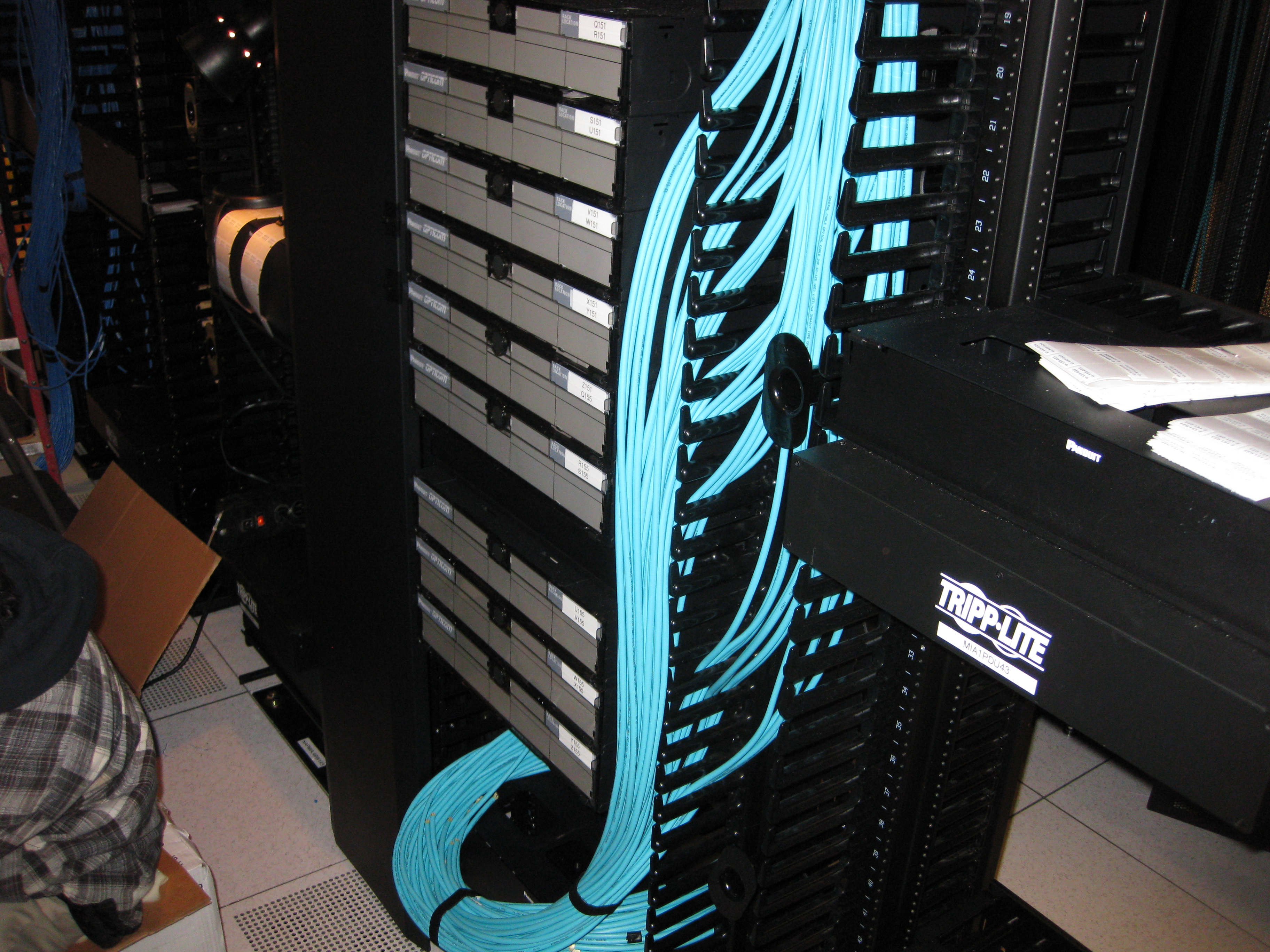
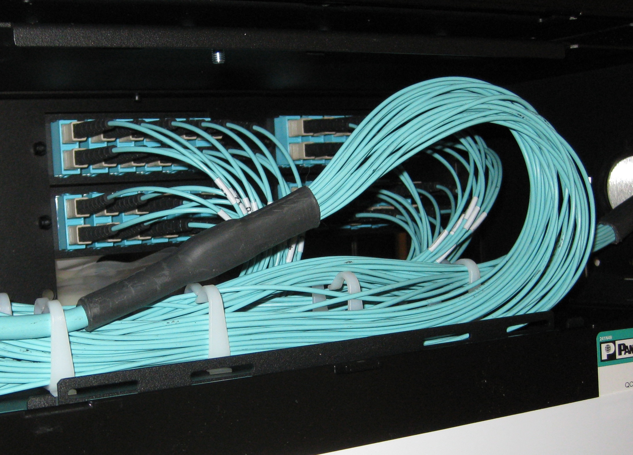
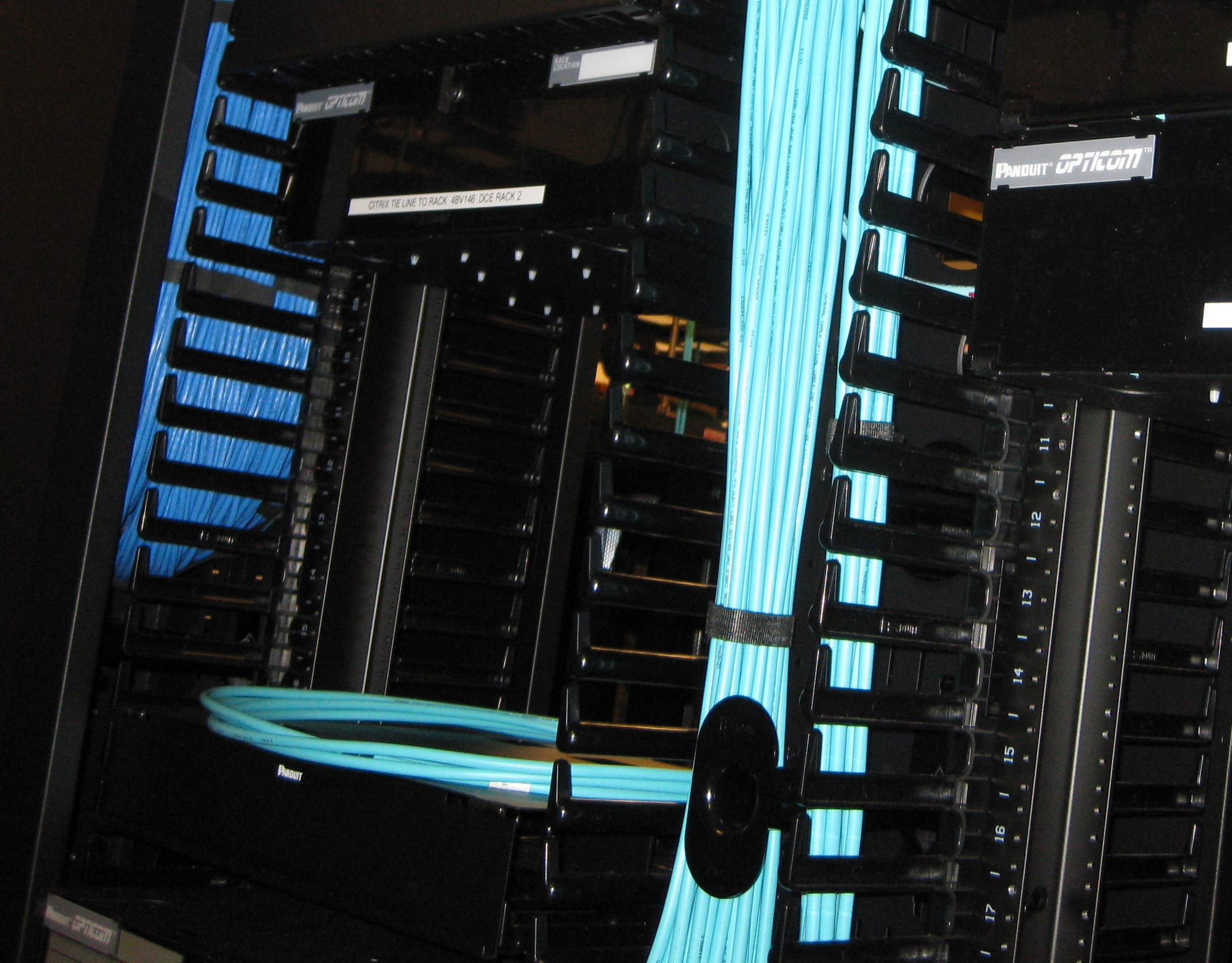
Representative equipment and examples of the systems our team installs and supports.
Often paired with this work.
Serving Tampa Bay and surrounding Florida markets.
We're based in Tampa and travel to job sites throughout the bay area and across Florida. If your project is in the region, we can be on site.
View all service areasPlanning a Low-Voltage Project?
Tell us about the site, scope, and schedule. We'll walk through the requirements and get you a clear, honest quote.